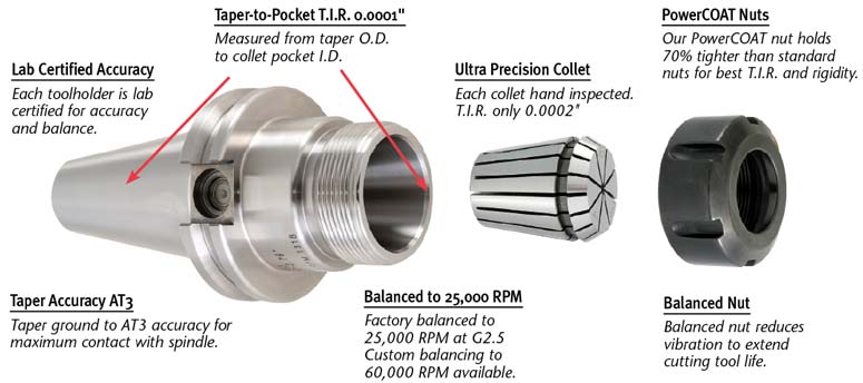
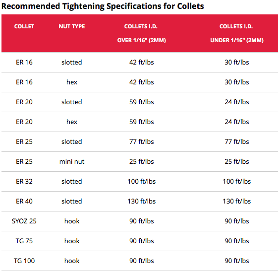
 Installing ER (DR, RD, ESX) , style collets is very common in every machine shop and tool & die shop, but is everyone doing it CORRECTLY? Did you know that there is a torque specification on your collets? Many people use a cheater bar to tighten down collets believing that the "tighter is better" but that's not always the case. Like all toolholding collets, ER style collets are spring collets with a 30 degree front taper and a 16 degree back taper (a "free releasing 'locking-taper" just like your steep taper toolholder)
0 Comments
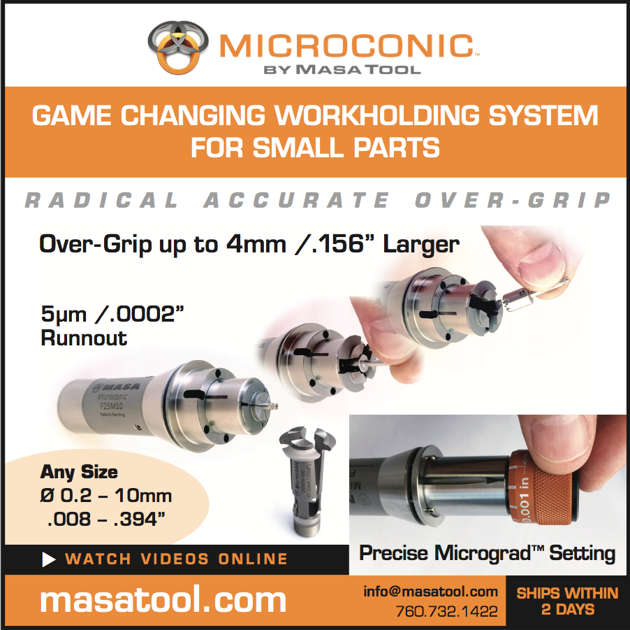
Matt Saccomanno, the inventor of the Microconic Workholding system discussed how it works at IMTS 2016. Masa Tool has developed the Microconic™ system specifically for holding workpieces from Ø0.15mm to 10mm (Ø0.006" to 0.390") in any machine that has a collet-type chuck.
Check out the video below where Matt explains the intricacies of the Microconic system during IMTS 2017 This article examines the difference between traditional SLA, DLP and 3SP for additive manufacturing in a large build envelope when high accuracy, repeatability, reliability and throughput are required. After more than three decades of research and development, 3D printing is ready for prime time in manufacturing — production of high-value parts and mass customized products, in addition to prototypes, injection molding tooling, end-of-arm tooling and assembly jigs and fixtures. In fact, a variety of manufacturers have been using 3D printing, also known as additive manufacturing, this way for years now, with more adopting the technology every day. In addition to manufacturers of all sizes, the range of production users also includes laboratories, hospitals and Hollywood studios. Did you know, for example, that the global hearing aid industry has been mass producing custom hearing aids with 3D printers for more than a decade1? In recent years, dental laboratories have also been mass producing dental and orthodontic models, which require high XY accuracy and a smooth surface finish. This has eased the way for the mass production of clear thermoformed aligners for teeth straightening, in addition to other dental products. And in 2016, General Electric began mass production of metal fuel nozzle injectors for its LEAP jet engine using 28 additive manufacturing machines — validating the idea that 3D printing isn’t just for prototypes anymore. 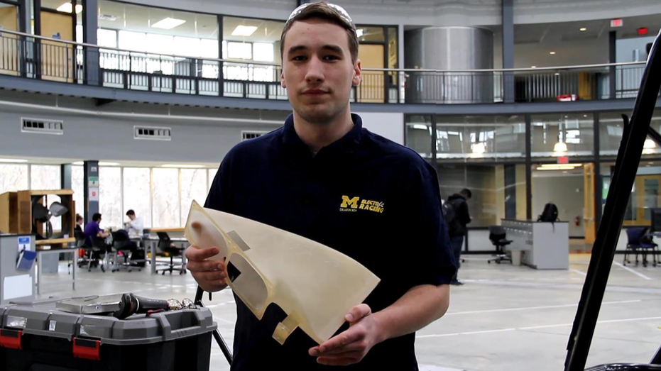 The University of Michigan-Dearborn chose EnvisionTEC’s large frame 3SP technology to 3D print large parts for its Formula SAE Electric race car project. Watch the video at EnvisionTEC.com/automotive Vat photopolymerization, in which a light source is used to selectively cure or harden photopolymer resins inside a vat or tray, has become a popular method of 3D printing among manufacturers for a variety of reasons. For example, the photopolymer resins used during this process are also known as thermosetting plastics or thermosets, which strengthen during post-curing and hold their shape, even after reheating. This is in contrast to thermoplastics, which can be re-melted after being formed into a part. A wide range of thermoset materials are also available today with a variety of desirable properties, such as epoxies, which offer elasticity and exceptional chemical resistance, as well as biocompatible materials. The vat photopolymerization category includes stereolithography (SLA), digital light processing (DLP) and a new method launched in 2013 called 3SP for scan, spin and selectively photocure. 3SP specializes in affordably building accurate parts with a smooth surface finish across a relatively large build envelope, where traditional SLA and DLP have challenges scaling up in size affordably. This allows for 3D printing of a single large part or a tray of smaller parts. To understand why 3SP is so unique in its benefits, it’s critical to understand the limits of SLA and DLP. Understanding SLA vs. DLPOne of the earliest forms of 3D printing, SLA was patented in 1986 and commercialized by 3D Systems.
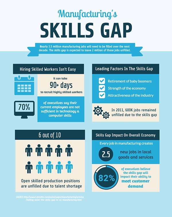
In SLA systems, a UV laser beam literally draws — lithography means “to write” — out a part into a vat of resin. Wherever the light hits resin, curing or hardening occurs. The laser beam can be positioned either above or directly below the vat, and each approach has its own pros and cons. However, for most large manufacturing systems, the laser is typically positioned above the vat and curing takes place on the upper layer of resin in the vat or tray. This approach allows for the largest build envelopes and lower gravitational forces on the part being built. After each layer is built onto a build platform inside the vat, the platform is lowered in the Z axis so the next layer can be cured onto the part. This article original appeared on Ganesh Machinery's Blog. DID YOU KNOW that over the next decade more than 3.5 million jobs will need to be filled? And according to The Manufacturing Institute, we will only be able to fill roughly 1.5 million of those jobs. With all of those jobs left unfilled, you can only imagine how many companies will get left behind because they lost the ability to produce. Take a look at the harsh reality we’re facing: Every year we see more reports and forecasts urging manufacturers to do something about the skills shortage. It’s time for us to do our part and we want to empower you to keep manufacturing alive and well in America. It starts with the youth.
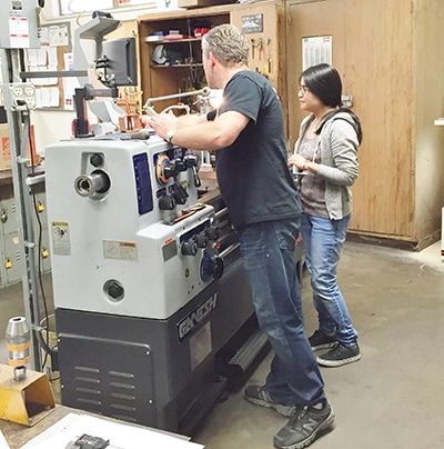
In December, we did just that. We donated our robust GT-1640 lathe to Simi Valley School and Institute to support their machinist training program. “The GT-1640 is ideal for this type of work because it is a powerful and precise lathe. It is also the type of machine students can expect to see when they enter the workforce,” said Simi Valley Lead Instructor Oygar Lindskog. >>Read the full story here. While it may seem like giving away a machine is a big chunk of change, we know it will pay off in the long run. It’s our contribution to educating and invigorating people so that manufacturing continues to grow and thrive in America for generations to come.
As passionate manufacturers, we want to see our industry grow and help incoming generations succeed. Let’s work together to make that happen.
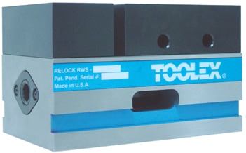
NOW AVAILABLE - Self Centering Vise for 5-Axis Applications.
 Moog is an American worldwide designer and manufacturer of motion and fluid controls and control systems for applications in aerospace, defense, industrial and medical device markets. Moog has manufacturing facilities in 26 countries around the world.
For their production facilities in Torrence CA, East Aurora NY and their plant in the Philippines Moog has selected 3nine’s products and could reduce their maintenance costs to a minimum. "Before installing the 3nine oil mist separator, we had to change filters every two weeks." ~ Jim Leach, Okuma Large Body Cell Machine Manager at MOOG Inc. Aircraft Group, USA Guest Blog by Cory Cetkovic, Product Manager, Sphinx, Big Kaiser Selecting the appropriate pilot drill is critical to maximize performance and tool life of a succeeding deep hole or micro drill. The purpose of a pilot drill is to create a clean, consistent working surface for the succeeding drill to enter the workpiece. Important aspects such as diameter tolerance and point angle (Figure 1) are often overlooked leading to inconsistent, unacceptable results. A pilot drill diameter should be slightly larger than nominal diameter, whereas the succeeding drill diameter should be smaller. This is often accomplished using positive and negative tolerances respectively (Figure 2). Selecting the incorrect pilot drill diameter can lead to premature failure of the succeeding drill as it will enter the pilot hole using its margins rather than its center-cutting point. It is also important for a pilot drill’s point angle to be equal to or larger than that of a succeeding drill. The purpose of a larger point angle is to guide the succeeding drill to centerline while preventing its corners from colliding with the point angle left by the pilot drill. Using a pilot drill with a smaller point angle usually results in chipped corners on the more expensive deep hole drill after drilling 10-20% of the expected tool life. 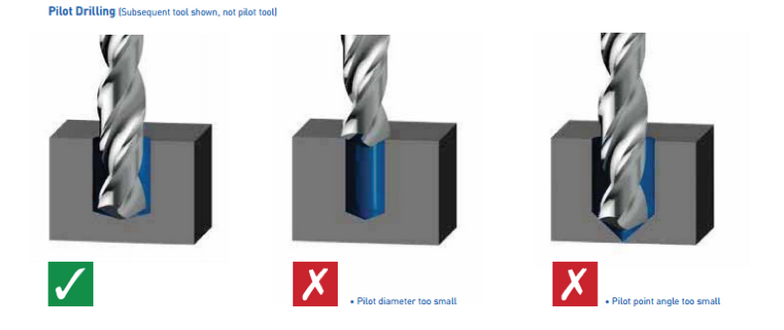 Figure 1. Three examples of a subsequent drill entering different pilot holes. The preferred situation with a pilot hole that has a larger diameter and point angle is identified with a green check mark. 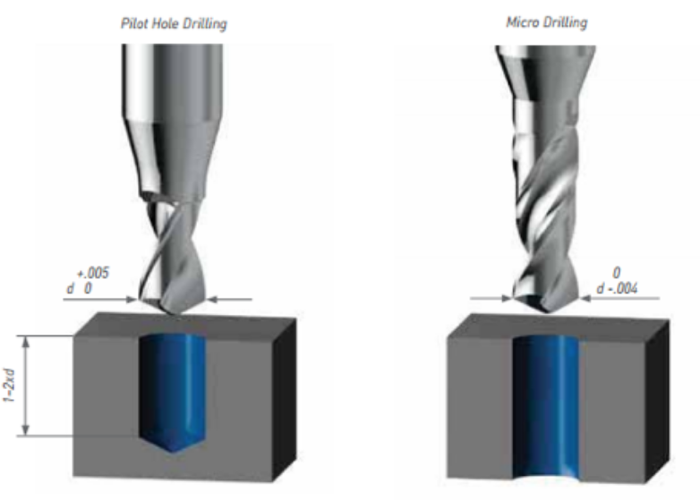 Figure 2. Demonstrates one method of achieving the appropriate pilot hole diameter. The pilot drill and succeeding drill have equivalent nominal diameters, but tolerances prevent the pilot hole from being smaller than the deep hole drill diameter. Oemeta presents a study on the environmental impact of cooling lubricants in metalworking Using Oemeta’s mineral oil-free, multifunctional HYCUT oil for metalworking significantly reduces the environmental impact when compared to an equivalent mineral oil-based cooling lubricant system. This was indicated in a study on environmental impact, conducted in collaboration with the Technical University of Braunschweig, in accordance with the standard life cycle assessment (LCA) method. In crankshaft production, one original equipment manufacturer (OEM) managed to save the equivalent of 470 tonnes of CO2 in one year. “We expected a good ecobalance, but both we and our customer were pleasantly surprised by just how positive the results were”, says Stefan Joksch, Technical Director at Oemeta. According to a study titled “Life Cycle Assessment of Metal Removal Fluid systems in metalworking applications – Evaluation of environmental impacts using the example of crankshaft manufacturing”, Oemeta’s HYCUT system can improve environmental values by up to 60%. The study was initiated by Oemeta, in collaboration with a German manufacturer of premium automobiles, and conducted by the Institute of Machine Tools and Production Technology at the Technical University of Braunschweig. It uses LCA to analyse the potential environmental impacts of mineral oil-free, multifunctional HYCUT oil, and compares these impacts to those of a conventional mineral oil-based lubricant system. In order to comprehensively evaluate a product’s environmental impacts, the product’s entire life cycle – from raw material extraction through to manufacture, use, and disposal – is taken into account. The assessment measures both the consumed resources, and the emissions produced along the life cycle of the product. This occurs across all of the examined processes, such as production and disposal processes, energy generation, transportation etc., and converts these values into environmental impacts. The results are related to an indicator substance. For example, global warming potential (GWP) is related to the indicator substance CO2 and given in kg CO2 equivalents. Carryover of metalworking fluids is not a problem The investigation was carried out as part of a case study on the process chain in crankshaft production, which looked at a diverse range of machining methods, such as milling, turning, deep drilling and grinding. As the process chain frequently alternates between steps involving water-miscible and non-water-miscible cooling lubricants, washing processes are integrated between the steps. Using ester-based, multifunctional HYCUT oil ensures that water-miscible and non-water-miscible components are compatible. This means that the introduction of metalworking fluids by means of adherence on components is no longer a concern. On the contrary: Oil that has been carried over is used as a lubrication performance in the emulsion during subsequent processing. Compared to mineral oil-based benchmark products, this results in a much more efficient use of cooling lubricants throughout the entire manufacturing line. Intermediate steps can be eliminated and metalworking fluid waste is practically non-existent. Reusing the washing agent, employed to clean the components, as a cooling lubricant during the manufacturing process also has a positive effect on the ecobalance. In summary, the use of the HYCUT system significantly reduced the environmental impacts (40-60%) in all of the categories examined throughout the entire life cycle. 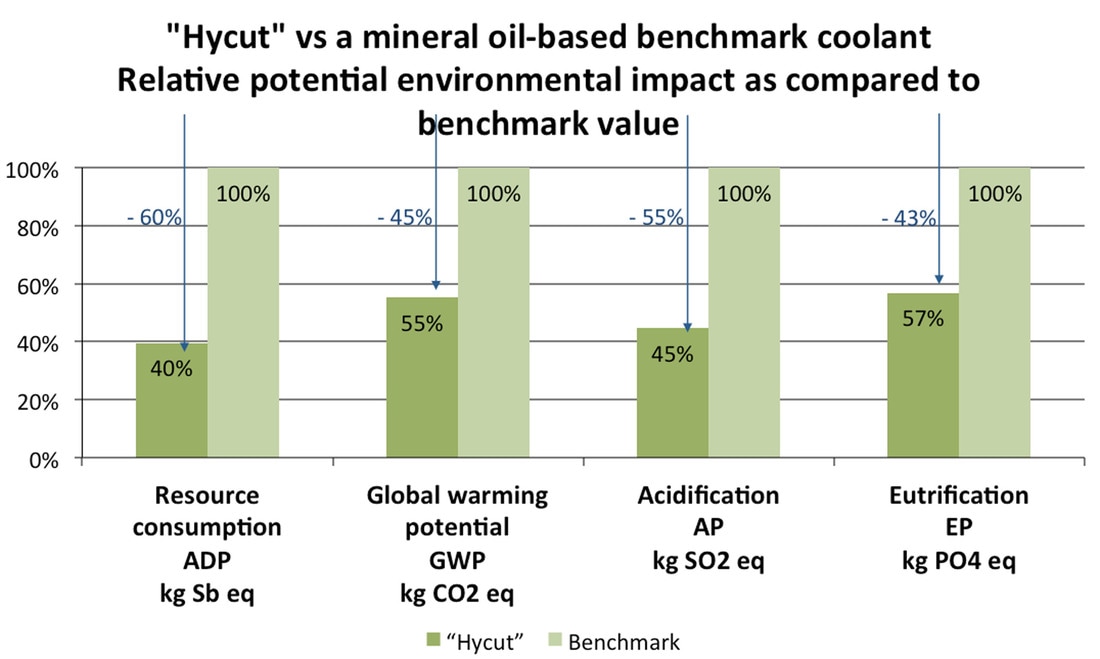 However, when machines are used incorrectly or without caution, damage to the wheel can occur. Be sure to follow the instructions below to ensure safe operation. 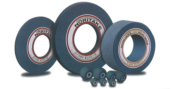 NORITAKE GRINDING WHEEL OPERATIONS AND HANDLING INSTRUCTIONS:
|
AuthorHere you will find the latest breaking news from manufacturing as well as the newest product introductions and promotions Archives
July 2017
Categories
All
|
||||||||||||||||
 RSS Feed
HoursM-F: 8am - 5pm
|
Telephone319.329.8134
|
|
©2023 Abrasive Innovations. All Rights Reserved